

![]() Attach
|
Attach
|
![]() Edit
|
Edit
|
![]() Revisions
Revisions
![]() Related Content
Related Content
IBM PC Camera Disassembly
Every Halloween, I'd set up a web cam for our haunted house to capture the festivity that goes on that night. This past Halloween is no exception. Except, the night before Halloween, I decided to modify the IBM PC Camera so that it can gather more light; more light in the IR and UV range. I wanted to light up our haunted house with IR and UV lights, which are invisible to the naked eye, so that I can get bright web cam photos without destroying the haunted house scene. (I've gone through a thorough explanation of how to use IR/UV lights to light up a scene in my Hacking Digital Cameras book.) This document shows the procedure of how to take the IBM PC Camera apart to get to the sensor.
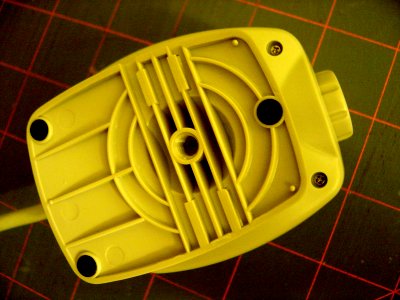
There are two small screws on the bottom of the IBM PC Camera as shown in the photo below. You might have to rotate the base to get to them.
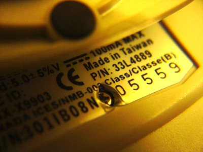
There is one hidden screw underneath the product label (see photo below). You'll have to rotate the base again to get to this screw. Simply poking through the label with your screwdriver is probably the easiest thing to do here.
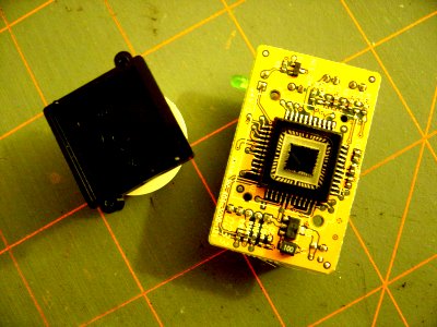
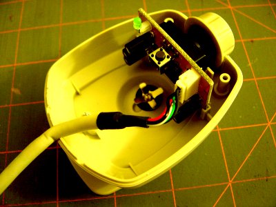
After removing the case cover, you can see that the sensor board and the lens takes up very little room in the case. There are a lot of empty space. Maybe it's time to think of ways to mod this case to add more features?

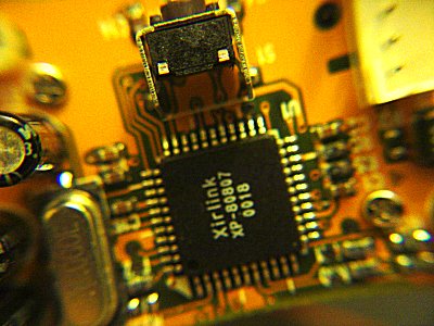
Removing the circuit board and you can see the Xirlink chip. The chip designation is clearly shown in the photo below. There are two tiny screws beside the chip that you'll need to remove. These screws fasten the lens over the image sensor.

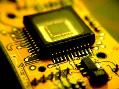
After removing the plastic lens, you'll uncover the image sensor on the circuit board, as shown in the photo below.
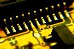
If you look at the image sensor, you'll see a piece of glass over it (see photo below). That is NOT the IR/UV glass filter (as Austin points out in the discussion thread for this article). Read the next paragraph on where it identifies the actual location of the IR/UV glass filter.

After taking my cam down to this level I did not see the tell tale red reflection on the chip level glass. That being said, I looked at the focus ring assembly and at least on my model camera there was indeed a small square glass piece that reflects red light. Problem solved! Well, almost. It seems that this small filter's location also serves to provide spacing of the small dome lens that is the camera's objective lens. Removing the filter and not keeping the objective lens to the REAR of the focus knob assembly! (keep it closest to the CMOS sensor) This will make the focusing still possible. - Austin C.
![]() Attach
|
Attach
|
![]() Edit
|
Edit
|
![]() Revisions
Revisions
![]() Related Content
Related Content
Attachments
- Chip Legs thumbnail.jpg (5 KB)
- IR and UV Filter Glass Covers the Imager Sensor.jpg (30 KB)
- Lens Off with the Imager Sensor Exposed.jpg (33 KB)
- Off with the Case.jpg (28 KB)
- Screw Underneath the Label.jpg (23 KB)
- Screws on the Bottom of the Camera.jpg (28 KB)
- Xirlink XP-80807 0018 Chip.jpg (35 KB)
447 Users Online
|
Get Our
$10000-above $5000-$9999 $2000-$4999 $1000-$1999 $500-$999 $200-$499 $100-$199 $50-$99 $25-$49 $0-$24 Gift Certificate 
|
|


