

![]() Add Comment
|
Add Comment
|
![]() Related Links
|
Related Links
|
![]() TrackBack
TrackBack
![]() Related Content
Related Content
Lose the preflash
Hi.
Being new to this site I thought that I would try a simple basic circuit to get started. It fires the camera on the second flash (the taking flash). Also fires the flash on the third flash by throwing the switch. It can make this a permanent 2 flash by eliminating the "and gate chip"
Attached Image: 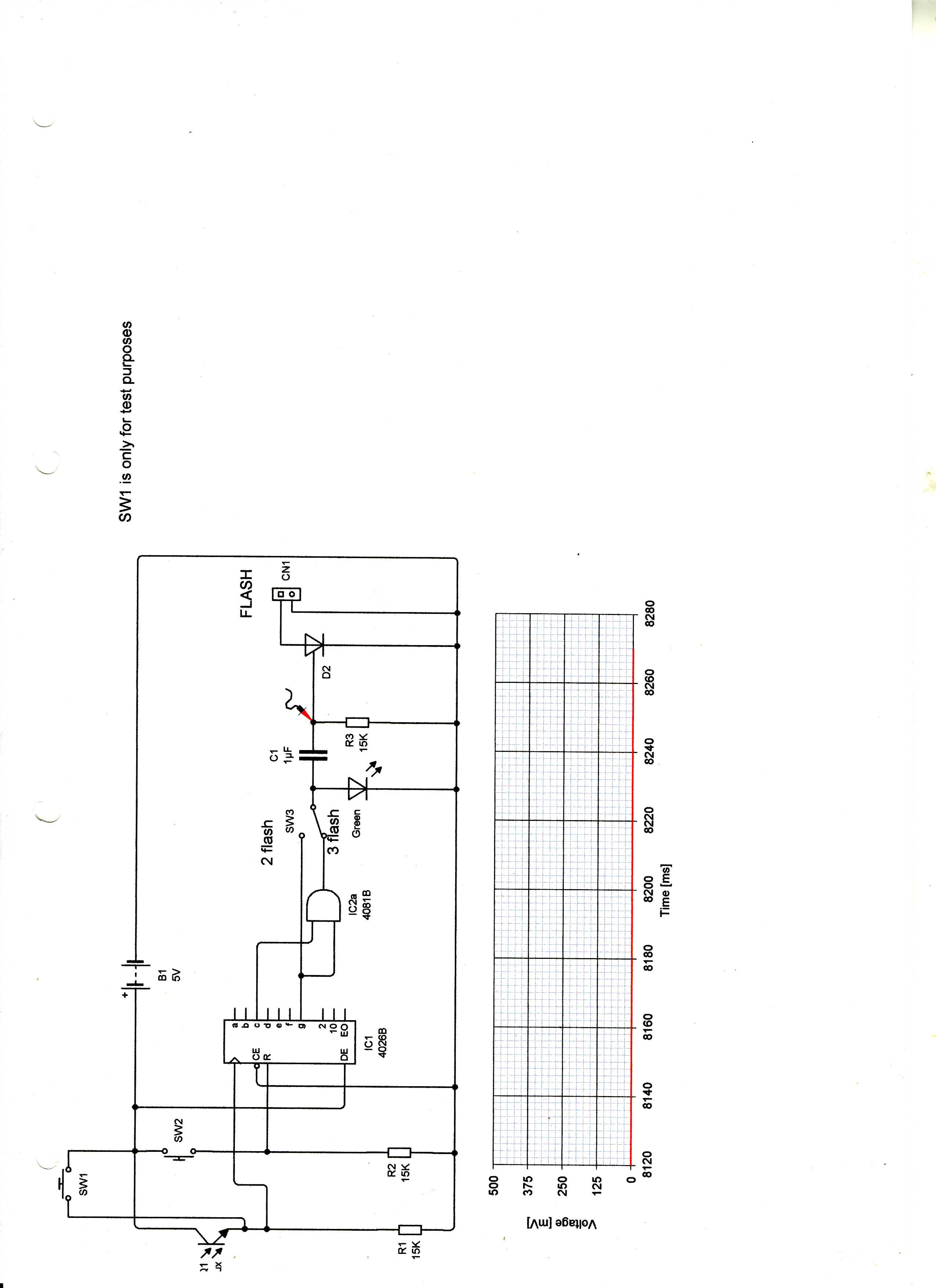
3 flash adaptor001.jpg
geriatric
Mon, 20 Sep 2010 11:15:05 +0000
here is a simpler circuit for a 2 flash adaptor. You could be ambitious and wire in a 7 segment display
Attached Image: 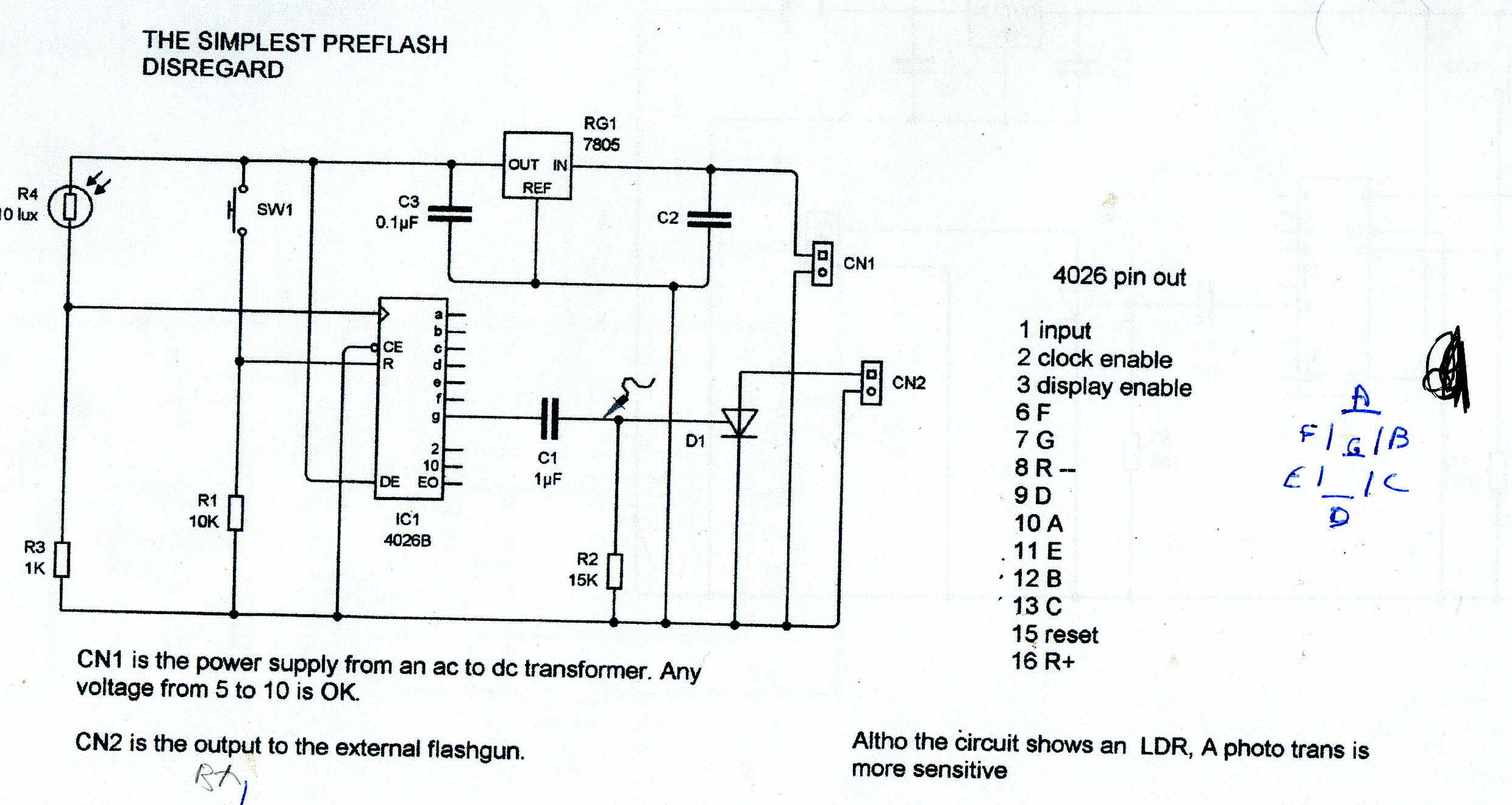
2 flash adaptor001.jpg
geriatric
Mon, 20 Sep 2010 12:39:52 +0000
Hi, geriatric. Thanks for updating these diagrams. But can you give us slightly more details on what is the purpose of these circuitry? It sounds like it triggers the camera to take a photo in the original post. What are some applications for this hack?
Chieh Cheng
Mon, 20 Sep 2010 15:30:23 +0000
When I designed these circuits everybody complained about the 2 flashes fired by the on board flash or a flash on the hotshoe. Let me explain the operation of a 4026 chip. It is known as a decade counter as it obviously counts up to 10. There are 7 led`s in a segment display lettered as a b c d e f g. When the unit is switched on all segments go high and light,except g otherwise it would show 8 insteasd of 0.The first pulse from the photo transistor to the input of the 4026 sending b & c high showing 1. G stays low so no effect on the led or capacitor. The second pulse (the main flash puse ) arrives, this now sends a b d e G high. As g goes high the capacitor is charged and a brief pulse is fed to the gate of the 106 scr. This puts the scr on and the main flash discharges through the scr.
geriatric
Mon, 20 Sep 2010 18:55:20 +0000
Here is a shot of the adaptor using a Vivitar flash. triggered by the on board flash. The green led lights on the second flash received. The red button is to reset the unit after a flash.
Attached Image: 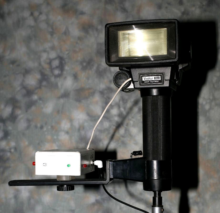
ASIVIVITAR DISREGARDER.jpg
geriatric
Mon, 20 Sep 2010 22:04:30 +0000
forgot to mention the 3 flash adaptor. The only difference is bsides the "G" connection there is a "C" connection to make both inputs to the "and gate" high thus charging the capacitor and pulsing the scr.
geriatric
Mon, 20 Sep 2010 22:14:32 +0000
Oh I see. I'm starting to get you. So the circuitry bypasses the pre-flash, but allows the main flash to fire, right?
Chieh Cheng
Wed, 22 Sep 2010 15:59:27 +0000
Exactly. I see nobody except you are interested in this project, so I will give it a rest.
geriatric
Thu, 23 Sep 2010 06:32:34 +0000
Don't fret it. There are a lot of lurkers on this forum.
Chieh Cheng
Thu, 23 Sep 2010 22:01:42 +0000
![]() Add Comment
|
Add Comment
|
![]() Related Links
|
Related Links
|
![]() TrackBack
TrackBack
![]() Related Content
Related Content
Did your message disappear? Read the Forums FAQ.
Add Comment
Spam Control | * indicates required field
TrackBack
TrackBack only accepted from WebSite-X Suite web sites. Do not submit TrackBacks from other sites.
Send Ping |
TrackBack URL |
No TrackBacks yet. TrackBack can be used to link this thread to your weblog, or link your weblog to this thread. In addition, TrackBack can be used as a form of remote commenting. Rather than posting the comment directly on this thread, you can posts it on your own weblog. Then have your weblog sends a TrackBack ping to the TrackBack URL, so that your post would show up here.
Messages, files, and images copyright by respective owners.
407 Users Online

$10000-above $5000-$9999 $2000-$4999 $1000-$1999 $500-$999 $200-$499 $100-$199 $50-$99 $25-$49 $0-$24 Gift Certificate 
|
|